Sunday, November 3, 2013
DIY Smartwatch: Test Screen
Here's just a quick video that provides a basic outline of what I want the watch GUI to look like. Feel free to provide comments and criticism!
DIY Smartwatch: Code Hosting
While I was waiting for my board to come in, I started playing with the screen, learning about Adafruit's library as well as designing the watch interface and visuals. I've created a Github repository to host all of the test programs, image files, and final code. I'm currently using a modified Adafruit GFX library and the SdFat library, but will probably strip out the code not required for my application and start using a custom display library soon.
DIY Smartwatch: Board Layout
After the circuit design comes the hard part, the board layout. I went through several iterations of trying to fit all of the different components on the board but essentially based the design around the Bluetooth module, which I knew I wanted on top, the screen header, which I wanted on the bottom, and the buttons which I wanted on the right side of the watch. Below is the fruit of many hours of labor. The board design is actually the stage which decided the final components I would use. During the circuit design phase I had included an RTC and crystal oscillator, but as you can see below, there wasn't really any room for it. I also figured that the internal oscillator on the AVR is reasonably accurate and the time could be included in a data packet sent from the phone.

The top layer of the board is a 3.3V pour and the bottom is a ground pour, but after adding all of the components to the board I noticed that the power would have to take a rather circuitous route to reach some of the components on the right side. To remedy this, I decided to add some last minute capacitors and shift some components around to provide better connectivity. However, in my rush I ended up making a few minor mistakes. Namely I placed several capacitors and components directly under the Bluetooth board.


And here are the fabbed boards! I ordered them from Fusion PCB since they are the cheapest option I could find and provided a quantity of ten boards in the event I made a lot of soldering mistakes. I only glanced at a few of the boards but am very satisfied with the quality. The only downside of their service is the turnaround time. It took twenty days from day of order to day of delivery, which is reasonable since they're based in China, but can be frustrating if you need to make multiple iterations and improvements.
Saturday, November 2, 2013
DIY Smartwatch: Circuit Design
This post is meant to be an explanation of the final schematic for my Smartwatch board, version 1 with a bit of reasoning behind each component and my reasoning behind why I did what I did.

This is just the reset button, connected to reset the AVR and BLE module. I also originally tied the screen reset to it as well until I realized the Adafruit screen library required it to be connected to a GPIO.

This is the vibration motor circuit. Since the motor uses up to 85mA, about twice what the AVR can supply, it's hooked up to an N-MOSFET to amplify the current. I also hooked up the gate of the MOSFET to a PWM pin on the AVR in case I don't need the full vibration. There is also a diode and capacitor attached to the leads of the motor to help reduce noise and prevent large voltage spikes.

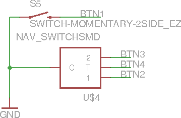
Next are the switches. The four-pin box above is actually a navigation switch with each pin being a connection for up, down, and press actions. Since the AVR has built in internal pull-up resistors, the switches are all tied to ground. I also quickly ran out of interrupt pins (there are four or five on this AVR but they also doubled as communication pins that I needed for other things) so am using PCINT pins instead. I have never used these before and they aren't built into the Arduino toolchain so we'll see how using them goes.

Here is the BLE module in all of its low power glory. I grabbed the eagle part over from the same place I got the breakout board and used his design as a reference. There are debugging LEDs on the TX, RX, and Connect lines to show the status of the BLE module, but odds are I won't be keeping these since LEDs take several mA and I won't have power to spare.

Above is the power regulation circuit. It takes the battery (3.4V - 3.7V) and regulates down to 3.3V. I also added a power switch at the last minute in case I want to solder the battery leads directly onto the PCB.

This is the charging circuit. It takes 5V power from the USB port and feeds it to a chip that handles the charging for me.

Next is the cheap 3-axis accelerometer I'm hoping to use for a good deal of the interactivity of the watch. However, it is a secondary feature so if I messed up it's not too big of a deal.
 Here's a simple brightness-detection circuit. I want to automatically control the brightness of the screen as a means of saving power so I've hooked up a photoresistor in a voltage divider circuit with the output being sent to an analog pin on the AVR.
 This is just the header for the screen.

Lastly is the AVR itself. In addition to the connections I've already covered there's also a voltage divider connected directly to the battery as a simple means of detecting the battery voltage as well as the USB data pins in the hopes that I can load the Arduino bootloader and program the watch directly from the computer.
 |
| Total Schematic Overview |
This is just the reset button, connected to reset the AVR and BLE module. I also originally tied the screen reset to it as well until I realized the Adafruit screen library required it to be connected to a GPIO.

This is the vibration motor circuit. Since the motor uses up to 85mA, about twice what the AVR can supply, it's hooked up to an N-MOSFET to amplify the current. I also hooked up the gate of the MOSFET to a PWM pin on the AVR in case I don't need the full vibration. There is also a diode and capacitor attached to the leads of the motor to help reduce noise and prevent large voltage spikes.
Next are the switches. The four-pin box above is actually a navigation switch with each pin being a connection for up, down, and press actions. Since the AVR has built in internal pull-up resistors, the switches are all tied to ground. I also quickly ran out of interrupt pins (there are four or five on this AVR but they also doubled as communication pins that I needed for other things) so am using PCINT pins instead. I have never used these before and they aren't built into the Arduino toolchain so we'll see how using them goes.

Here is the BLE module in all of its low power glory. I grabbed the eagle part over from the same place I got the breakout board and used his design as a reference. There are debugging LEDs on the TX, RX, and Connect lines to show the status of the BLE module, but odds are I won't be keeping these since LEDs take several mA and I won't have power to spare.

Above is the power regulation circuit. It takes the battery (3.4V - 3.7V) and regulates down to 3.3V. I also added a power switch at the last minute in case I want to solder the battery leads directly onto the PCB.

This is the charging circuit. It takes 5V power from the USB port and feeds it to a chip that handles the charging for me.

Next is the cheap 3-axis accelerometer I'm hoping to use for a good deal of the interactivity of the watch. However, it is a secondary feature so if I messed up it's not too big of a deal.


Lastly is the AVR itself. In addition to the connections I've already covered there's also a voltage divider connected directly to the battery as a simple means of detecting the battery voltage as well as the USB data pins in the hopes that I can load the Arduino bootloader and program the watch directly from the computer.
Thursday, October 24, 2013
DIY Smartwatch: I've got competition!
So it looks as if I'm not the only one looking to design a fun, interactive watch. A very cool OLED watch was recently featured on Hackaday. It has all sorts of features crammed into it and looks like was an impressive amount of time and effort put into making it. Watching a video of the watch in action gave me lots of thoughts about what to implement in my design and reading his write-up gave me a chance to compare my methods and parts against his. Overall I really like his design and what he did with such little space, and I would ultimately like to achieve the level of detail, quality, and battery life that he did, though with a slightly bigger package.
That being said, my design remained relatively unchanged after looking at his, mainly because we are attempting to accomplish different tasks and most of our circuitry was already similar. I did update my design to use the navigation button seen on his watch, but that will have little effect in the long run.
That being said, my design remained relatively unchanged after looking at his, mainly because we are attempting to accomplish different tasks and most of our circuitry was already similar. I did update my design to use the navigation button seen on his watch, but that will have little effect in the long run.
DIY Smartwatch: Other Components
With the main component of the watch being chosen, it's now time to choose everything else that will go into making this watch. Since I chose a higher end screen, I'm going to shoot for other nicer components in order to get the most functionality out of it.
First off is the processor. I chose an Atmega32u4 for several reasons.
- I'm very familiar with Arduino and AVR programming, plus the Arduino community has phenomenal support so I wanted a chip that was also on an Arduino board, namely the Atmega328p or Atmega32u4.
- I chose the Atmega32u4 because it has more pins, more memory, more Flash, and a built in USB core which would mean no extra chip required for USB programming. The extra memory and Flash are also a plus since graphical programming result in a pretty large memory footprint.
- As an added plus, the Atmega32u4 has a way to internally change the processor speed so if it becomes an issue, I can speed up the chip when I need a speed boost.
For the Bluetooth 4.0 module I chose a module from FastTech mostly due to the fact that someone had already done all of the hard work, making an eagle component and breakout board.
I also decided to use this accelerometer from Sparkfun since it was the cheapest that they have and also has orientation and shake interrupts that I foresee using in the watch.
I decided to use this vibration motor from Sparkfun since it was already in their eagle library and I was making a purchase from them already.
I added the LiPo charging IC found on this board for to charge my battery directly from USB power.
And for the last of the major components I'm using a generic photocell to detect brightness
Aside from that I have a few other minor components such as regulators, headers, transistors, and passive components with a full BOM to be posted later.
Friday, October 18, 2013
DIY Smartwatch: Silent but not Idle
It may have been over a month since I've posted anything, but I've certainly been productive in that time! I've gotten quite a few things done including making the bill of materials, circuit design, and board design as well as ordering everything I should need for the finished product. Now that I'm waiting for everything to arrive, it's time to catch up on the documentation.
Over the next few days I'm going to try and write posts for how I established all of the other components to include in the circuit, how I designed the circuit itself, and how I designed the board. The lines between these topics also became quite blurred as I went on so I'm only going to cover the finished product and briefly discuss how I arrived there.
In the past month another DIY watch similar to what I plan also popped up over at Hackaday so I may also take a post to comment on what I liked from that design, what I didn't, and overall what I thought of it.
Lastly, I noticed a pretty neat competition over at Instructables that I may try and enter, assuming I finish by the Nov 11th deadline. Grand prize is a new laptop, 2nd gen Nexus 7, and quadcopter. It looks like the requirements are very broad, it has to be designed with a microcontroller, so hopefully I'll be entering this watch as well as my Pi on the Face project.
Subscribe to:
Posts (Atom)