- Possibly use the onboard voltage regulator on the Adafruit display
- The Adafruit display board already has a 3.3V regulator for the screen logic, using this would mean one less part that I need and would give me a tiny bit extra space.
- Maybe just switch to the E-Ink display to save power
- I was very dismayed by the enormous amount of power the screen uses. Even if I get tricky and heavily optimize the screen usage, I'm not sure how long I can get the battery to last. This is a last ditch solution and would probably involve an entire re-layout of the board.
- Use through holes for the battery instead of a connector
- The battery connector is the tallest component on the board aside from the connectors, getting rid of it would mean I can make the uber-thick watch a little bit thinner. Since I have verified that the battery charging circuit works, I just need to decide which battery will be used I should then be able to solder it in permanently.
- Use micro USB instead of mini
- Same thing as above, the mini USB is pretty tall. A micro USB connector didn't seem much harder to solder and would give me a little extra space.
- Get rid of reset button
- When I'm entirely done programming the watch, I'll most likely give it a simple case, making the Reset button entirely inaccessible anyway. It might be better for space to replace the button with a test point.
- Add real-time clock
- With the added space from removing components, there might be room for an RTC that could be used to keep better track of time.
- Enlarge accelerometer pads for easier soldering
- As previously stated, the accelerometer is very difficult to solder, especially without a hot air station. If I don't decide to buy one, another option might be to enlarge the pads for the accelerometer chip connections so it is easier to touch with the soldering iron.
- Move tall components away from microSD slot on display board
- In line with the USB and battery connections, I need to plan ahead so that the top boards fits better with the bottom board with less wasted space.
- Silk screen labels
- Since I rushed to ship out the board for fab, I didn't take the time to properly and clearly label all the components on the board. Doing so would make identifying what needs to go where much easier and would make debugging simpler if I know what vias are attached to what.
- Test points
- It would probably help to have some dedicated test points to make sure the circuit is behaving as it should be.
Monday, June 23, 2014
DIY Smartwatch: Improvements for V2
From the current progress I've already made on this project, I can already see a lot of mistakes and things that will need to be improved for the second PCB. Below is a list of the ones that immediately come to mind.
DIY Smartwatch: Soldering SMD
Going into this project I knew I would have to do a lot of surface mount soldering to save space and money. I used the smallest SMD hand-solderable packages and still ran out of space! I've never been particularly good at soldering, but knew that I would have to become much better to tackle the types of projects I'm interested in. In anticipation of this, I splurged and bought a very nice soldering iron from Radioshack. I cannot express how great this iron is! I'm used to using cheap, $10 irons that just need to get the job done, but with the fine tip on my new one, SMD wasn't difficult at all! Below is a picture of the board with most of the components soldered on.
{INSERT IMAGE}
{INSERT IMAGE}
You'll notice that I haven't yet soldered on the accelerometer. That's because QFN packages are much smaller than I anticipated, even with a fine tipped iron. In order to solder this, I'd probably need solder paste and a hot air station, something I'm not quite ready to drop $100 on yet. Not sure what I'm going to do about that, especially since I'm going to need the accelerometer to minimize power usage.
Tuesday, November 5, 2013
DIY Smartwatch: Screen Current Draw
To give a better idea of the power budgeting I'll be working with, I wrote a small test program to cycle through various percentages of the screen set to white with varying brightness levels. Since black pixels on OLED displays are completely turned off, they consume no power and so a power saving method is to use darker tones. That is why I'm testing the screen at various "ON" percentages. As for the brightness, this display uses a 4 bit value to determine how bright the display will be set to with the brightness being in increments of 1/16. Below is a table relating current draw to percentage of the screen on and the brightness for a 5V supply.
| 0/15 | 1/15 | 2/15 | 3/15 | 4/15 | 5/15 | 6/15 | 7/15 | 8/15 | 9/15 | 10/15 | 11/15 | 12/15 | 13/15 | 14/15 | 15/15 | |
|---|---|---|---|---|---|---|---|---|---|---|---|---|---|---|---|---|
| 0% | 6.1 mA | 6.4 mA | 6.5 mA | 6.7 mA | 6.8 mA | 6.7 mA | 6.8 mA | 6.8 mA | 7.0 mA | 7.1 mA | 7.1 mA | 7.1 mA | 7.2 mA | 7.4 mA | 7.4 mA | 7.4 mA |
| 25% | 17.1 mA | 20.8 mA | 24.9 mA | 29.1 mA | 32.8 mA | 36.2 mA | 39.9 mA | 42.4 mA | 44.3 mA | 46.2 mA | 47.9 mA | 49.0 mA | 49.7 mA | 52.1 mA | 52.6 mA | 53.4 mA |
| 50% | 28.1 mA | 35.5 mA | 43.5 mA | 51.4 mA | 58.8 mA | 65.7 mA | 73.5 mA | 79.7 mA | 81.9 mA | 85.3 mA | 89.2 mA | 91.2 mA | 92.6 mA | 97.1 mA | 97.8 mA | 99.6 mA |
| 75% | 39.6 mA | 50.7 mA | 62.6 mA | 74.2 mA | 85 mA | 95.6 mA | 107.5 mA | 118.8 mA | 121.3 mA | 125.4 mA | 131.2 mA | 134.4 mA | 141.5 mA | 143.2 mA | 144.4 mA | 146.7 mA |
| 100% | 51.1 mA | 66.2 mA | 82.2 mA | 97.1 mA | 111.5 mA | 125.5 mA | 139.2 mA | 152.6 mA | 160.8 mA | 167.3 mA | 174.3 mA | 177.7 mA | 186.8 mA | 189.2 mA | 191.5 mA | 195.2 mA |
That's quite a lot more than what I originally thought the display would draw. It looks like I'm going to have to do some serious power budgeting to make up for this.
Sunday, November 3, 2013
DIY Smartwatch: Test Screen
Here's just a quick video that provides a basic outline of what I want the watch GUI to look like. Feel free to provide comments and criticism!
DIY Smartwatch: Code Hosting
While I was waiting for my board to come in, I started playing with the screen, learning about Adafruit's library as well as designing the watch interface and visuals. I've created a Github repository to host all of the test programs, image files, and final code. I'm currently using a modified Adafruit GFX library and the SdFat library, but will probably strip out the code not required for my application and start using a custom display library soon.
DIY Smartwatch: Board Layout
After the circuit design comes the hard part, the board layout. I went through several iterations of trying to fit all of the different components on the board but essentially based the design around the Bluetooth module, which I knew I wanted on top, the screen header, which I wanted on the bottom, and the buttons which I wanted on the right side of the watch. Below is the fruit of many hours of labor. The board design is actually the stage which decided the final components I would use. During the circuit design phase I had included an RTC and crystal oscillator, but as you can see below, there wasn't really any room for it. I also figured that the internal oscillator on the AVR is reasonably accurate and the time could be included in a data packet sent from the phone.

The top layer of the board is a 3.3V pour and the bottom is a ground pour, but after adding all of the components to the board I noticed that the power would have to take a rather circuitous route to reach some of the components on the right side. To remedy this, I decided to add some last minute capacitors and shift some components around to provide better connectivity. However, in my rush I ended up making a few minor mistakes. Namely I placed several capacitors and components directly under the Bluetooth board.


And here are the fabbed boards! I ordered them from Fusion PCB since they are the cheapest option I could find and provided a quantity of ten boards in the event I made a lot of soldering mistakes. I only glanced at a few of the boards but am very satisfied with the quality. The only downside of their service is the turnaround time. It took twenty days from day of order to day of delivery, which is reasonable since they're based in China, but can be frustrating if you need to make multiple iterations and improvements.
Saturday, November 2, 2013
DIY Smartwatch: Circuit Design
This post is meant to be an explanation of the final schematic for my Smartwatch board, version 1 with a bit of reasoning behind each component and my reasoning behind why I did what I did.

This is just the reset button, connected to reset the AVR and BLE module. I also originally tied the screen reset to it as well until I realized the Adafruit screen library required it to be connected to a GPIO.

This is the vibration motor circuit. Since the motor uses up to 85mA, about twice what the AVR can supply, it's hooked up to an N-MOSFET to amplify the current. I also hooked up the gate of the MOSFET to a PWM pin on the AVR in case I don't need the full vibration. There is also a diode and capacitor attached to the leads of the motor to help reduce noise and prevent large voltage spikes.

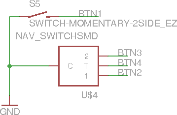
Next are the switches. The four-pin box above is actually a navigation switch with each pin being a connection for up, down, and press actions. Since the AVR has built in internal pull-up resistors, the switches are all tied to ground. I also quickly ran out of interrupt pins (there are four or five on this AVR but they also doubled as communication pins that I needed for other things) so am using PCINT pins instead. I have never used these before and they aren't built into the Arduino toolchain so we'll see how using them goes.

Here is the BLE module in all of its low power glory. I grabbed the eagle part over from the same place I got the breakout board and used his design as a reference. There are debugging LEDs on the TX, RX, and Connect lines to show the status of the BLE module, but odds are I won't be keeping these since LEDs take several mA and I won't have power to spare.

Above is the power regulation circuit. It takes the battery (3.4V - 3.7V) and regulates down to 3.3V. I also added a power switch at the last minute in case I want to solder the battery leads directly onto the PCB.

This is the charging circuit. It takes 5V power from the USB port and feeds it to a chip that handles the charging for me.

Next is the cheap 3-axis accelerometer I'm hoping to use for a good deal of the interactivity of the watch. However, it is a secondary feature so if I messed up it's not too big of a deal.
 Here's a simple brightness-detection circuit. I want to automatically control the brightness of the screen as a means of saving power so I've hooked up a photoresistor in a voltage divider circuit with the output being sent to an analog pin on the AVR.
 This is just the header for the screen.

Lastly is the AVR itself. In addition to the connections I've already covered there's also a voltage divider connected directly to the battery as a simple means of detecting the battery voltage as well as the USB data pins in the hopes that I can load the Arduino bootloader and program the watch directly from the computer.
 |
| Total Schematic Overview |
This is just the reset button, connected to reset the AVR and BLE module. I also originally tied the screen reset to it as well until I realized the Adafruit screen library required it to be connected to a GPIO.

This is the vibration motor circuit. Since the motor uses up to 85mA, about twice what the AVR can supply, it's hooked up to an N-MOSFET to amplify the current. I also hooked up the gate of the MOSFET to a PWM pin on the AVR in case I don't need the full vibration. There is also a diode and capacitor attached to the leads of the motor to help reduce noise and prevent large voltage spikes.
Next are the switches. The four-pin box above is actually a navigation switch with each pin being a connection for up, down, and press actions. Since the AVR has built in internal pull-up resistors, the switches are all tied to ground. I also quickly ran out of interrupt pins (there are four or five on this AVR but they also doubled as communication pins that I needed for other things) so am using PCINT pins instead. I have never used these before and they aren't built into the Arduino toolchain so we'll see how using them goes.

Here is the BLE module in all of its low power glory. I grabbed the eagle part over from the same place I got the breakout board and used his design as a reference. There are debugging LEDs on the TX, RX, and Connect lines to show the status of the BLE module, but odds are I won't be keeping these since LEDs take several mA and I won't have power to spare.

Above is the power regulation circuit. It takes the battery (3.4V - 3.7V) and regulates down to 3.3V. I also added a power switch at the last minute in case I want to solder the battery leads directly onto the PCB.

This is the charging circuit. It takes 5V power from the USB port and feeds it to a chip that handles the charging for me.

Next is the cheap 3-axis accelerometer I'm hoping to use for a good deal of the interactivity of the watch. However, it is a secondary feature so if I messed up it's not too big of a deal.


Lastly is the AVR itself. In addition to the connections I've already covered there's also a voltage divider connected directly to the battery as a simple means of detecting the battery voltage as well as the USB data pins in the hopes that I can load the Arduino bootloader and program the watch directly from the computer.
Subscribe to:
Posts (Atom)