Tuesday, November 5, 2013

DIY Smartwatch: Screen Current Draw

To give a better idea of the power budgeting I'll be working with, I wrote a small test program to cycle through various percentages of the screen set to white with varying brightness levels.  Since black pixels on OLED displays are completely turned off, they consume no power and so a power saving method is to use darker tones.  That is why I'm testing the screen at various "ON" percentages.  As for the brightness, this display uses a 4 bit value to determine how bright the display will be set to with the brightness being in increments of 1/16.  Below is a table relating current draw to percentage of the screen on and the brightness for a 5V supply.


0/15 1/15 2/15 3/15 4/15 5/15 6/15 7/15 8/15 9/15 10/15 11/15 12/15 13/15 14/15 15/15
0% 6.1 mA 6.4 mA 6.5 mA 6.7 mA 6.8 mA 6.7 mA 6.8 mA 6.8 mA 7.0 mA 7.1 mA 7.1 mA 7.1 mA 7.2 mA 7.4 mA 7.4 mA 7.4 mA
25% 17.1 mA 20.8 mA 24.9 mA 29.1 mA 32.8 mA 36.2 mA 39.9 mA 42.4 mA 44.3 mA 46.2 mA 47.9 mA 49.0 mA 49.7 mA 52.1 mA 52.6 mA 53.4 mA
50% 28.1 mA 35.5 mA 43.5 mA 51.4 mA 58.8 mA 65.7 mA 73.5 mA 79.7 mA 81.9 mA 85.3 mA 89.2 mA 91.2 mA 92.6 mA 97.1 mA 97.8 mA 99.6 mA
75% 39.6 mA 50.7 mA 62.6 mA 74.2 mA 85 mA 95.6 mA 107.5 mA 118.8 mA 121.3 mA 125.4 mA 131.2 mA 134.4 mA 141.5 mA 143.2 mA 144.4 mA 146.7 mA
100% 51.1 mA 66.2 mA 82.2 mA 97.1 mA 111.5 mA 125.5 mA 139.2 mA 152.6 mA 160.8 mA 167.3 mA 174.3 mA 177.7 mA 186.8 mA 189.2 mA 191.5 mA 195.2 mA

That's quite a lot more than what I originally thought the display would draw.  It looks like I'm going to have to do some serious power budgeting to make up for this.

Sunday, November 3, 2013

DIY Smartwatch: Test Screen

Here's just a quick video that provides a basic outline of what I want the watch GUI to look like.  Feel free to provide comments and criticism!


DIY Smartwatch: Code Hosting

While I was waiting for my board to come in, I started playing with the screen, learning about Adafruit's library as well as designing the watch interface and visuals.  I've created a Github repository to host all of the test programs, image files, and final code.  I'm currently using a modified Adafruit GFX library and the SdFat library, but will probably strip out the code not required for my application and start using a custom display library soon.

DIY Smartwatch: Board Layout

After the circuit design comes the hard part, the board layout.  I went through several iterations of trying to fit all of the different components on the board but essentially based the design around the Bluetooth module, which I knew I wanted on top, the screen header, which I wanted on the bottom, and the buttons which I wanted on the right side of the watch.  Below is the fruit of many hours of labor.  The board design is actually the stage which decided the final components I would use.  During the circuit design phase I had included an RTC and crystal oscillator, but as you can see below, there wasn't really any room for it.  I also figured that the internal oscillator on the AVR is reasonably accurate and the time could be included in a data packet sent from the phone.

The top layer of the board is a 3.3V pour and the bottom is a ground pour, but after adding all of the components to the board I noticed that the power would have to take a rather circuitous route to reach some of the components on the right side.  To remedy this, I decided to add some last minute capacitors and shift some components around to provide better connectivity.  However, in my rush I ended up making a few minor mistakes.  Namely I placed several capacitors and components directly under the Bluetooth board.


And here are the fabbed boards!  I ordered them from Fusion PCB since they are the cheapest option I could find and provided a quantity of ten boards in the event I made a lot of soldering mistakes.  I only glanced at a few of the boards but am very satisfied with the quality.  The only downside of their service is the turnaround time.  It took twenty days from day of order to day of delivery, which is reasonable since they're based in China, but can be frustrating if you need to make multiple iterations and improvements.

Saturday, November 2, 2013

DIY Smartwatch: Circuit Design

This post is meant to be an explanation of the final schematic for my Smartwatch board, version 1 with a bit of reasoning behind each component and my reasoning behind why I did what I did.
Total Schematic Overview


This is just the reset button, connected to reset the AVR and BLE module.  I also originally tied the screen reset to it as well until I realized the Adafruit screen library required it to be connected to a GPIO.


This is the vibration motor circuit.  Since the motor uses up to 85mA, about twice what the AVR can supply, it's hooked up to an N-MOSFET to amplify the current.  I also hooked up the gate of the MOSFET to a PWM pin on the AVR in case I don't need the full vibration.  There is also a diode and capacitor attached to the leads of the motor to help reduce noise and prevent large voltage spikes.


Next are the switches.  The four-pin box above is actually a navigation switch with each pin being a connection for up, down, and press actions.  Since the AVR has built in internal pull-up resistors, the switches are all tied to ground.  I also quickly ran out of interrupt pins (there are four or five on this AVR but they also doubled as communication pins that I needed for other things) so am using PCINT pins instead.  I have never used these before and they aren't built into the Arduino toolchain so we'll see how using them goes.


Here is the BLE module in all of its low power glory.  I grabbed the eagle part over from the same place I got the breakout board and used his design as a reference.  There are debugging LEDs on the TX, RX, and Connect lines to show the status of the BLE module, but odds are I won't be keeping these since LEDs take several mA and I won't have power to spare.


Above is the power regulation circuit.  It takes the battery (3.4V - 3.7V) and regulates down to 3.3V.  I also added a power switch at the last minute in case I want to solder the battery leads directly onto the PCB.


This is the charging circuit.  It takes 5V power from the USB port and feeds it to a chip that handles the charging for me.


Next is the cheap 3-axis accelerometer I'm hoping to use for a good deal of the interactivity of the watch.  However, it is a secondary feature so if I messed up it's not too big of a deal.

Here's a simple brightness-detection circuit.  I want to automatically control the brightness of the screen as a means of saving power so I've hooked up a photoresistor in a voltage divider circuit with the output being sent to an analog pin on the AVR.


This is just the header for the screen.


Lastly is the AVR itself.  In addition to the connections I've already covered there's also a voltage divider connected directly to the battery as a simple means of detecting the battery voltage as well as the USB data pins in the hopes that I can load the Arduino bootloader and program the watch directly from the computer.

Thursday, October 24, 2013

DIY Smartwatch: I've got competition!

So it looks as if I'm not the only one looking to design a fun, interactive watch.  A very cool OLED watch was recently featured on Hackaday.  It has all sorts of features crammed into it and looks like was an impressive amount of time and effort put into making it.  Watching a video of the watch in action gave me lots of thoughts about what to implement in my design and reading his write-up gave me a chance to compare my methods and parts against his.  Overall I really like his design and what he did with such little space, and I would ultimately like to achieve the level of detail, quality, and battery life that he did, though with a slightly bigger package.

That being said, my design remained relatively unchanged after looking at his, mainly because we are attempting to accomplish different tasks and most of our circuitry was already similar.  I did update my design to use the navigation button seen on his watch, but that will have little effect in the long run.

DIY Smartwatch: Other Components

With the main component of the watch being chosen, it's now time to choose everything else that will go into making this watch.  Since I chose a higher end screen, I'm going to shoot for other nicer components in order to get the most functionality out of it.

First off is the processor.  I chose an Atmega32u4 for several reasons.
  • I'm very familiar with Arduino and AVR programming, plus the Arduino community has phenomenal support so I wanted a chip that was also on an Arduino board, namely the Atmega328p or Atmega32u4.
  • I chose the Atmega32u4 because it has more pins, more memory, more Flash, and a built in USB core which would mean no extra chip required for USB programming.  The extra memory and Flash are also a plus since graphical programming result in a pretty large memory footprint.
  • As an added plus, the Atmega32u4 has a way to internally change the processor speed so if it becomes an issue, I can speed up the chip when I need a speed boost.
For the Bluetooth 4.0 module I chose a module from FastTech mostly due to the fact that someone had already done all of the hard work, making an eagle component and breakout board.

I also decided to use this accelerometer from Sparkfun since it was the cheapest that they have and also has orientation and shake interrupts that I foresee using in the watch.

I decided to use this vibration motor from Sparkfun since it was already in their eagle library and I was making a purchase from them already.

I added the LiPo charging IC found on this board for to charge my battery directly from USB power.

And for the last of the major components I'm using a generic photocell to detect brightness

Aside from that I have a few other minor components such as regulators, headers, transistors, and passive components with a full BOM to be posted later.

Friday, October 18, 2013

DIY Smartwatch: Silent but not Idle

It may have been over a month since I've posted anything, but I've certainly been productive in that time!  I've gotten quite a few things done including making the bill of materials, circuit design, and board design as well as ordering everything I should need for the finished product.  Now that I'm waiting for everything to arrive, it's time to catch up on the documentation.

Over the next few days I'm going to try and write posts for how I established all of the other components to include in the circuit, how I designed the circuit itself, and how I designed the board.  The lines between these topics also became quite blurred as I went on so I'm only going to cover the finished product and briefly discuss how I arrived there.

In the past month another DIY watch similar to what I plan also popped up over at Hackaday so I may also take a post to comment on what I liked from that design, what I didn't, and overall what I thought of it.

Lastly, I noticed a pretty neat competition over at Instructables that I may try and enter, assuming I finish by the Nov 11th deadline.  Grand prize is a new laptop, 2nd gen Nexus 7, and quadcopter.  It looks like the requirements are very broad, it has to be designed with a microcontroller, so hopefully I'll be entering this watch as well as my Pi on the Face project.

Monday, September 16, 2013

DIY Smartwatch: Screen Hunting

First thing's first, the main component of the watch is going to be the screen.  Almost all functionality and features (interaction, battery life, display, notification style, etc.) will be dependent on what the screen is and how it works.  The main hobby stores I follow are Adafruit and SparkFun so below I've listed X different screens that I found and would be suitable given my constraints.  I also find a good portion of my electronics on eBay but most of the displays I found there were just cheap knock-offs of the Adafruit and SparkFun designs and I'd much rather get the main component of my project from a reputable source with lots of example code instead of a questionable one.  The displays I found also came with breakout boards which added 5-10mm to both dimensions so ultimately I think I'll be using the screen dimensions as the final dimensions for the finished product.

Primary Criteria:

  • 45x45mm
  • Low Power - less than 50mA
  • Greater than 1.25" diagonal
  • Easy to interface
Secondary Criteria:

  • Color
  • Touchscreen
  • $40 or less


Adafruit:


  • SHARP Memory Display Breakout - 1.3" 96x96 Silver Monochrome
    • Dimensions - 40x40mm
    • Power Consumption - Nothing specific listed on the site, but after going through Sharp's spec sheets it looks like power consumption stays under 5mA for constant updating and drops down to under 10uA for a static image.
    • Interface - SPI with easy to use library
    • Price - $40
SparkFun:

  • Serial Miniature OLED Module - 1.5"
    • Dimensions - 45.5x33.5mm
    • Power Consumption - 40mA average
    • Interface - Serial
    • Price - $50
    • Bonus - SD card holder, onboard graphics processor
So I'm going to rule out the SparkFun modules right off the bat.  While the idea of getting a large screen with a built in microcontroller is appealing, I'm already going to be spending a lot of time figuring out how to program the watch and making the Android app so I'd rather just use an AVR chip since I'm familiar with them.  In addition, these modules are roughly $10 more than their dumb counterparts, whereas an AVR chip only costs a few dollars.  The Nokia module is also surplus and rather old so it might arrive in questionable condition and I'd rather future proof this watch as much as possible by making the most expensive component of the watch robust, futuristic, and nice to look at.

This leaves me with the monochrome OLED, SHARP memory display, and color OLED.  Since the monochrome and color OLEDs both have similar power consumption, I'm going to rule out the monochrome one in favor of the using the full range of color.  So ultimately the decision comes down to two very nice displays at $40 each, with both displays having their benefits and drawbacks.

On the one hand, the SHARP display has negligible power consumption which is a big concern, but it has slower update rates, is monochrome, and is a write only display, meaning the entire image must be stored in memory, taking up valuable program space.  The color OLED display has a respectable range of color, a higher resolution, a faster update rate, but consumes far more power.

Ultimately, I'm in favor of the color OLED display.  Making this watch will be a long term project, with many upgrades and tweaking along the way, so I'd like to get the nicer display now, deal with the lesser battery life in the short term, and upgrade to a nicer battery later or just carry around a spare.  It will also act as incentive to optimize power consumption and create some power saving algorithms that could apply to future projects.

Sunday, September 15, 2013

DIY Smartwatch: Project Definitions

Now that I've reviewed what the current smartwatch offerings are, it's time to define a set goals for my own version.

Primary Goals:

  • Size (<= 45x45x10mm) - Regular watch sizes vary from 34mm to 40mm with larger ones reaching up to 44mm.  The smartwatches on the market tend toward the larger end of the spectrum so I'm going to set a hard limit at 45mm x 45mm size, with a push for smaller.  Thickness is another matter entirely.  Most hobbyist screens on the market need a breakout board which means my watch will need to have two PCBs and a battery sandwiched together.  The commercial offerings average at a thickness of 10mm so I'm going to shoot for around there.
  • Connectivity (BLE) - This is a simple one.  My phone supports BLE and battery life is going to be a huge issue so I'm going to try cutting power consumption wherever I can.  BLE is the obvious choice and there are a couple of cheap modules available on eBay.
  • Screen ( > 1.25") - This choice will be largely dependent on my power budget and how power hungry the options for screens are.  However, since no screen on any of the watches currently offered is less than 1.25" diagonally, I think that's a good minimum goal to shoot for.  In terms of screen technology I assume I'm going to have to use some sort of OLED or low power LCD since the eInk type displays offered on the hobbyist market are still pretty sparse.  Maybe I'll get lucky, but I would definitely like to have a color screen if at all possible.
  • Battery Life (8 hours) - Since I'm attempting to make a nice smartwatch that has similar functionality to commercial offering, I'm obviously going to have to make sacrifices somewhere.  It's probably going to end up being in the battery life category.  I can't afford low power components and don't have the means to solder tiny chips onto a PCB.  I also don't have much choice when it comes to hobby batteries' sizes and shapes so I will be using the best possible options.  All these factors combined means I'm going to set a goal for an 8 hour battery life so it can last through a whole work day.  Worst case scenario, I can get multiple batteries and swap them out when necessary.
  • Price (<= $100) - As stated in my previous post, early supporters of the Pebble smartwatch could get one for $100 and that seems like a reasonable amount, so I'll set a hard limit at that price, though hopefully it will end up being cheaper.
  • Interactivity - This one is pretty much up in the air.  I'm experienced enough in Android programming that I can do a lot of the settings and notification handling on the phone side of things, but I would like to add some functionality to the watch as well.  If I get lucky I'd like to use a touchscreen but I'm not sure how likely it is to find one in the right size so I'll probably end up with a few tactile switches for selection and most of the controls.  I'd also like notifications to trigger something more noticeable than the screen lighting up so I'd like to add a vibration motor or a status LED as well.  Additionally, I think an accelerometer would be a useful sensor to add since it probably uses negligible power and could be used for gesture recognition and other interfacing ideas.

Monday, September 9, 2013

DIY Smartwatch: Current Offerings

Time for the most important step of the design process: the product definition.  I'm going to take some time, research some examples, and write down specifically what I (would) want in a custom smartwatch.  Let me start off by outlining the features of some current smartwatches on the market and using them to zero in on what I want.

Battery life:
  • Pebble - Roughly 7 days, mostly due to the ePaper display
  • Galaxy Gear - Roughly one day
  • Qualcomm Toq - 3 to 4 days
  • Sony SmartWatch 2 - 3 to 4 days
Screen:
  • Pebble -
    • Sharp Memory or ePaper which means no color, just black and white, but has a backlight
    • 1.26"
    • 144x168 pixels
  • Galaxy Gear - 
    • Super AMOLED display which means lots of bright vibrant colors and no power draining backlight
    • 1.63"
    • 320x320 pixels
  • Qualcomm Toq - 
    • Mirasol Color Display, similar to eInk but with color, pretty low power usage
    • 1.55"
    • 288x192 pixels
  • Sony SmartWatch 2 -
    • Transflexive LCD which I assume means some sort of low power LCD screen
    • 1.6"
    • 220x176 pixels
Size:
  • Pebble - 32mm (W) x 50.33mm (H) x 8.44mm (D)
  • Galaxy Gear - 36.8mm (W) x 56.6mm (H) x 11.1mm (D)
  • Qualcomm Toq - 47.6mm (W) x  43.3mm (H) x 9.96mm (D)
  • Sony SmartWatch 2 - 42mm (W) x  41mm (H) x 9mm (D)

Connectivity:
  • Pebble - Bluetooth 2.1 or 4.0 (BLE)
  • Galaxy Gear - Bluetooth 4.0 (BLE)
  • Qualcomm Toq - Bluetooth 4.0
  • Sony SmartWatch 2 - Bluetooth 3.0, NFC
Interactivity:
  • Pebble - 4 navigation buttons, accelerometer for dismissing notifications with a shake, magnetometer, ambient light sensor
  • Galaxy Gear - Camera, 2 microphones, speaker, accelerometer, gyroscope, interactions with S Voice and other Galaxy features, touchscreen
  • Qualcomm Toq - touchscreen
  • Sony SmartWatch 2 - touchscreen
Price:
  • Pebble - $150
  • Galaxy Gear - $300
  • Qualcomm Toq - $300
  • Sony SmartWatch 2 - $180
So as a whole, the smartwatches on the market now have a lot to offer.  I probably won't be able to achieve the same resolution as any of the commercial offerings, but I think I can at least get some of the same features.  Size might also end up being an issue.  I'll most likely need to find a balance between features and size constraints.  Price is also worth mentioning.  $150 for the cheapest smartwatch is pretty steep.  The early backer price for the Pebble on Kickstarter was $100 so I'm going to try and shoot for less than that price range.

Sunday, September 8, 2013

DIY Smartwatch: Why do I care?

With Google Glass popularity on the upswing, Sony releasing its second generation of SmartWatch, and the recent releases of the Samsung Galaxy Gear and Qualcomm Toq, it's a great time for the wearable technology industry.  Since the advent of mobile phones, technology has become less a tool and more an extension of our selves.  While thirty years ago a computer was merely a high functioning calculator designed to accomplish work more easily, computers are now a ubiquitous tool that we carry in our pockets, carrying out tasks ranging from the mundane to critical.  As computers becomes more integral to our daily lives, technology companies will be focusing more and more on ease of use and availability of new technology.  The architectures of the notification systems in Android, iOS, and Windows phones are structured around streamlining the process of updates in one's personal life by making notifications noticeable and informative, yet subtle and accessed with the minimal amount of effort possible.

Smartwatches and Google Glass are what technology companies are hoping is the next step in making this process even easier for the consumer.  Why should a person need to go through the hassle of taking a phone out of their pocket, turning on the screen, and sifting through notifications when the same notification system can be grafted onto a device that is already always available.  Furthermore, with battery life in cell phones making minimal improvements over the past few years, it is even more important to remove the number one cause of battery drain, powering the screen.  Watches and Google Glass are meant to serve as a platform that consumers can use to keep in touch with their notifications and online presence without needing to separate themselves from their surroundings by taking the time to look down at their phones.  A watch is made for the occasional glance, used to inform oneself of the current time.  A smartwatch can be the same, with updates reflected directly on the screen so the user can quickly see if they need to respond to a notification.

Now personally, I don't believe smartwatches are all that cool.  Sure, it's another nifty little gadget, but it doesn't really add anything.  I don't really find taking my phone out of my pocket to be that big of a hassle.  However, I do think smartwatches are the first big technology that can be replicated by the Maker community.  In fact one of the first popular smartwatches, the Pebble, was created as a Kickstarter project.  I think it would be pretty fun and education to try and make a serviceable smartwatch so, time allowing, I might add it as another project on my list of things to do with blog posts documenting my process.

Saturday, August 17, 2013

Into the Sky: Hours 1-2

So in the first two hours of my project, I've programmed some basic GUI code.  I'm using Java and Swing for the front end since I have a good deal of experience with it.  The way I see it, an RPG needs a few core features in the GUI: A way to display stats, inventory, skills, etc., a console for displaying messages and chats, and a main screen to display whatever is happening in the RPG world.  I decided that I would use a sidebar on the left side of the screen with tabs for Stats, Skills, and Inventory with a Text Area at the bottom for displaying item/skill/stat descriptions.  Then the main screen would be on the right side above the chat/console window.  Everything is thrown together using JSplitPanes so that the user can customize the sizing of all the elements based on how the like it.  I started with the main code and adjusted down to the subcomponents since I prefer a top down approach.  The final product is in the picture below and all of the code is available at my github at https://github.com/kelliott121/IntoTheSky.

You'll notice the sidebar has separate tabs for each category, making it pretty easily expandable.  At some point I will probably add a settings or some such.  I've also included some example items for each tab.  The bottom console has a text area for displaying console messages and a text input area for chatting.  Lastly there's the screen, where I've implemented a small example for how it will be set up.  I'm using the JPanel class with a GridBagLayout and making a 2D array of JLabels with ImageIcons for the background images.  Since I'm shooting for a D&D style grid based game, I figured this would make it the easiest to implement.

Thursday, August 15, 2013

Game Design Project

One of the main types of coding projects I periodically come back to is game design, with my preference being RPGs.  As a kid, I played a handful of MMORPGs and some D&D, and at one point aspired to be a writer.  Since then I've ended up quite a ways from publishing my own novels, but I still enjoy thinking up entertaining fantasy and scifi scenarios as a creative outlet.  One bonus of being able to program is that I actually have the capability to implement some of these scenarios in the form of a game (assuming the art doesn't need to be above a 3rd grade level).

So I've fiddled around with a few RPG programming projects in the past couple of years, with none of them really going anywhere.  Just the other day, I started another one I've been conceptualizing for a couple of months.  Last spring my roommates and I started doing weekly D&D sessions, but after graduation it's been pretty much impossible for us to set aside time to learn the online D&D tools in addition to the hours it could take for a single gaming session.  Parallel to that, I also pondered about a science fiction game focusing on early space travel for humanity.  I personally enjoy science fiction shows and books about humanity's crawl from where we are now to an interstellar society.  I find near future, or at least futures heavily rooted in the present, settings to be the most compelling.  So I thought about different ideas for how we could reach the technology of interstellar travel and how that would relate to an RPG.

Since I will most likely never get to the point where I can design a high end 3D game, I've decided to shoot lower and attempt to combine the story I was creating with the game mechanics of Dungeons and Dragons.  This way I can hopefully one day soon continue my gaming sessions with my roommates in addition to providing myself a creative outlet.  With work, however, I can usually only average one or two productive hours a day, so I'm going to try and break down my design process on this blog hour by hour.  This way I'll be able to have an in depth view of how my game develops and hopefully some input from readers.

Wednesday, August 14, 2013

Life Update

It's been a while since my last post, and quite a bit has happened in my life.  I've graduated University of Delaware with my Bachelor's and have two classes left until I finish my Master's Degree, which I hope to do this Winter.  I will be taking this classes remotely from my new home in Pittsburgh, where I'm also working full time at Aerotech Inc, a motion control solutions company.  I've been there for about a month now, and it's been very interesting so far.  I've learned quite a bit about how larger companies operate as well as some professional programming styles.  I'll most likely be working very closely with DSPs and FPGAs, and I look forward to learning a lot about them!

Saturday, March 2, 2013

The Deconstruction

***Developing***
Last weekend I had the great opportunity to participate in a 48hr hackathon.  Called The Deconstruction, it involved a 48hr marathon where teams people from any age or background got together and built a project of our choice.  Aside from some of the creepy messages we got from trolls on our stream, it was awesome!  I think setting aside everything and taking a weekend to concentrate on making something is great and really spurs creativity.  I'm just lucky school is still slow and I didn't have much work.

So on to the project.  Ever since last summer, I've wanted to build an automatic drink mixing machine.  I even spent a fair bit of time planning it out and ordered some of the parts.  When I presented the idea to my teammates they all jumped on board and we decided to do that this weekend.  Our team was The Dangerous Dijkstras.  A lot of details about the construction of the project are at the team site.

Here are some videos of the final project.


Super Xilinx Kart

So here's an attempt at documenting an old project from last semester.  In my Computer Systems Design class we worked with Spartan 3E 500 FPGAs and we could do basically anything we wanted for the final project.  So a friend and I decided to make a Mario Kart clone.  We used the Xilinx ISE, XPS version 10.4 and Verilog.  All the graphics and hardware controls for the game are written in software.  Everything else is pure hardware.  Essentially we implemented a rudimentary GPU that performs graphics transformations in hardware to overcome the speed limitations of linear processing.    Lastly note that most of this is lifted from the written report so please excuse the formal tone and any grammar mismatches.


We drew a lot of our inspiration from the game Super Mario Kart on the Super Nintendo. This game
utilizes a hardware rendering mode called “mode 7.” In “mode 7” a perspective transform is applied to a background bitmap which gives the illusion of a 3D plane. Our foremost goal in this project was to get this mode working on the FPGA in hardware.

Super Mario Kart Screenshot
Notice how you can clearly see the difference between the character sprites and transformed 2D background


In addition to “mode 7” we also wanted to implement a general purpose hardware framework.
Processors with low clock speeds and small memories often have a hard time rendering large, complex
graphical scenes in real time. We set out to design a coprocessor that could render any graphical scene
you could throw at and make it all addressable from software. To do this we once again took inspiration from video game consoles of the past. We wanted to build a sprite system where sprites could be loaded from software into special purpose buffers that would allow for fast rendering. We would additionally have buffers for background bitmaps that we could apply the perspective transforms to.


Transforms

Pipeline
Proof of concept tests for Rotation, Translation, and Perspective transform equations


The main image processing section of our hardware uses a three stage processing pipeline to create the
3D effect. In 2D vga games, pixel values are fed into differing components which output an RGB value that is given to the display. In our design, the same pixel values (X and Y on the screen) are fed into a
pipeline which applies three separate transforms to get a resulting X,Y location. This location is fed into a component which contains a hardware synthesized course map. The course map is what finally
outputs the RGB color that is fed into the VGA module. By mapping these screen locations to an internal course map via different image transforms, the illusion of three dimensions can be created.


The first stage of the pipeline handles image translation. Our goal was to keep the player at the center
of the screen at all times. Using the position of the player, we shifted the course map to achieve this.


The next stage was rotation. Since sprites implemented in software are very costly in terms of memory, we chose to keep number low. Rotating the map to accommodate the player's orientation allowed us to extend the 3D effect as well as use one sprite for all situations.


Lastly was the unsuccessful perspective transform. The intent of this transform was to expand the
course map as the screen_y increased to give the appearance of depth and a horizon. While initially
successful, results of the perspective transform were warped after a bug fix in the translation transform.  Translation was set as a higher priority than perspective and due to lack of time a solution was never established.

It is worth noting that the perspective transform is the most mathematically complicated of the three and as such it was hard to create a perfect perspective transform without spending more time than was possible devoted to the mathematics.  In the Java mock up for the different transforms, the transform matrix above was used to generate proportionately scaled perspective, however, we found out that implementing exponentiation with variables was incredibly difficult with FPGAs and so a workaround had to be used that resulted in the disproportionate perspectives seen above.

Sprites
Sprites are graphical objects that are handled separately from the rest of a scene in graphical overlays.
They are a method of integrating unrelated bitmaps in order to create a full scene. The main benefit of
sprites is that they use a very small amount of memory and processing power compared to rendering a
full scene. They consist of a series of bitmaps that can be overlaid on the rest of the scene that the graphics processor is rendering. This means that the processor only has to keep track of the location of the sprite and it’s position, or animation progress. Below you can see an example of a sprite sheet from Super Mario Kart.


As you can see each of the squares contains Mario riding his kart in a different orientation. Game
programmers can use this sheet to make Mario rotate without using any advanced graphics processing
features (such as the transforms discussed in the previous section).

High Level Design
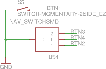
Our project is based on the Xilinx Spartan-3E FPGA chip. We used MicroBlaze, a softcore CPU provided by Xilinx in their Platform Studio, as the primary processor in our game and complemented it with a custom graphics coprocessor. We’re using onboard BRAM to store our program, which allows for optimal performance. We also have two additional hardware blocks, a button controller and an RS232 module, which provide input and debugging respectively. This is all outlined below in the system level block diagram.
Graphics Co-Processor
The graphics coprocessor is probably the most interesting part of the project. Our goals were to
implement “mode 7” as well as a software addressable sprite system. We did partially meet those goals. In the end our coprocessor supported 2 of the 3 transforms required to achieve “mode 7”. In our implementation we have the translation and rotation transforms working. While this does not provide an emulated 3D it still makes the game much more interesting. Additionally, we got the sprite system partially functional, due to hardware limitations we were only able to implement 2 sprite blocks at one time. This limited us to having two non-background objects on the screen at any one time. Below is a block diagram of how these modules interact with one another.


Game play
The Game play aspect of Super Xilinx Cart exists primarily in software, in accordance with our goals. We created two player objects, one for the computer and one for the player. The Microblaze processor reads the states of three buttons on the FPGA board and decides how to proceed based on that input.
  1.  Left Button rotates map clockwise
  2. Right Button rotates map counter-clockwise
  3. Down button moves the map in the opposite direction of the player, making it appear as if the kart is moving forward
Some very basic boundary avoidance groundwork has been created. The center of the default course
has a blue square which represents a pool of water. If the player enters the boundary of the water, they are placed back at the start. This groundwork provides an example of addition boundary and obstacle avoidance that could be implemented in the future to improve upon the game. For example, this could be used to count laps once the player crosses the finish line, detect collisions with other players, and allow for speed changes over different terrain. 

Lastly is the creation of a computer player. To demonstrate competitive nature of all racing games,
we've created a second sprite which stays close to the player throughout their run. It randomly swerves from side to side but slowly advances on the player's position. The goal of the player is to finish the race before the computer player passes them.

Design Challenges
The primary constraint on all aspects of this design was time. Finding time to focus and plan out the
design for this project proved more difficult than anticipated.

Another large challenge was the mathematics involved in the transformation pipeline. Implementing
the three transforms required study and derivation of several complex equations based on concepts in
linear algebra and computer graphics. The limitation of the hardware in this regard also proved rather
difficult. Due to the nature of FPGA's no existing sine and cosine functions are implemented and so
large lookup table modules had to be created. Additionally, to provide a smooth perspective transform with convincing depth perception, a second order differential equation was required, but hardware constraints limited the implementation to linear systems. Because of this the accuracy of the depth was sacrificed for ease of implementation.

Timing also proved to be an issue in the case of hardware design. The transformation pipeline
introduced large propagation delays into the system with the maximum clock frequency limited to
around 35MHz. The Microblaze and system clocks were brought down to 30MHz to compensate.

A smaller challenge that we faced was the complex nature of our project going beyond the realm of
conventional Xilinx Tool Usage. We had to learn our way around some of the more complex Xilinx tools in order to achieve the level of hardware control required for this project.

And lastly, I've included a video of the final working game.  While I really wish there had been time to get the 3D perspective working, I'm still very happy with the result.

Thursday, February 21, 2013

Pie on the Face

So the head mounted display turned out to be a success!  I now have a mobile Linux box with the following supplies.

  • Spy Gear Video Car headset - As mentioned previously it runs on component video signals sent via a stereo audio cable.  After buying a stereo jack and component connector from Radioshack, I hacked together an adapter to put power and component on the stereo cable.
  • Raspberry Pi - For those not familiar with it, it's a $35 Linux box with low power draw and a decent CPU.  It has the option for a component video out with was critical for making this project work.
  • Backup USB Battery - I bought one of these for $40 a while back to give extra juice to my tablet and phone, but it's turned out to be useful for other USB powered devices, such as the Raspberry Pi.  By connecting it to the 1A output port, it can power the Raspberry Pi.  Since the Raspberry Pi has a maximum current draw of 750mAh, it can run for roughly 16 hours.  The Raspi also has a GPIO header with 5V and ground pins so I can use that as power input for the video headset.  With some testing I verified that the display can work down to roughly a 3V input.
So after putting everything together, there were still a few kinks to work out.  The display itself is only 320x240 which is half VGA resolution.  It's also rather small and a little blurry, making it very difficult to see text since the display scales down the 640x480 resolution the Pi puts out.  The display is also rigged to work with PAL video signals and the Raspberry Pi puts out NTSC by default so that also had to be changed.  The way to fix both of these is to edit the config.txt file in the /boot/ directory.  By adding the line
sdtv_mode=2
The default video format was set to PAL.  The resolution required a little more tweaking.  It seems that you can't change the actual resolution of the Pi, but you can change the pixel width.  This is controlled by the framebuffer_width and framebuffer_height settings.  By setting it 320x240, I was able to change the display show properly, but this proved to be too difficult to see.  By halving it again to 160x120, the text is pretty much clear, albeit very large.

All in all this project has a lot of potential so I'll update the blog as I accomplish more things.

Sunday, January 27, 2013

New Phone!

For the past two years I've been using the Samsung Captivate, which is a variant of the Galaxy S, as my phone.  It's an Android phone and has served me well.  However, when I originally bought it I didn't realize how much I would love it.  It was really the only Android phone available on AT&T at the time and since I knew I didn't want an iPhone, it's what I got.  Let me just say I got very lucky.  As I've recently learned, the Captivate was used as a model for the Nexus S phone by Samsung and since the Nexus line always receives updates straight from Google, it was fairly easy for developers to port the newest Android versions to the Captivate as well.  This leads me to why I love the phone.  The software that it came with was pretty crappy.  Samsung was not considered the nicest manufacturer at the time, and was trying to throw out tons of phones in attempt to battle the iPhone.  As such, my phone wasn't slated for many software updates and the skinned version of Android wasn't it top shape.  Because of the many crashes I had to endure over the life of my warranty, I decided to root it once it expired.

Using Heimdall and the CyanogenMod website as a guide, I managed to successfully root it and install CyanogenMod 7.0.  It was an amazing change of pace to say the least.  New options were suddenly open to me.  Instead of software created by a huge corporation with little concern for providing all the bells and whistles, I was suddenly using an amazing culmination of the thoughts, ideas, and innovations coded by the developers over at XDA.  Features that I didn't even realize I wanted were suddenly open to me.  It felt like an entirely new phone.  And for someone like myself who always wants to stay on the cutting edge, the amount of ongoing development was wonderful.  I could easily reflash new ROMs on my phone and stay up to date with the newest versions of Android.  Over the past year I've kept my phone merely weeks behind the latest version of Android, something manufactures can't claim to have accomplished.  In fact, via XDA my Captivate is currently running Android 4.2.1, Jelly Bean, which is actually an upgrade ahead of my new phone.

Deciding on a replacement for the second most valuable piece of tech in my life (the first being my laptop of course) proved exceedingly difficult.  The Android market has changed drastically in the past two years and as such there are a huge number of options available, and while I try to keep up with the latest and greatest in mobile technology, I still had no clue what I wanted.  After some thought on the phones available on my new carrier, Verizon, I narrowed my options down the Samsung Galaxy SIII and recently released HTC Droid DNA.

The SIII was an amazing piece of hardware, with a huge following and massive developer community.  It also was, and still is, the most successful Android device.  The main drawback, however, was the fact that the phone was around 8 months old, which is an eternity in mobile years.  With a dual core processor, it had a hard time competing with newer devices, at least as far as benchmarks are concerned.

The DNA, on the other hand, was barely a month old and had a quad core processor and 1080p display.  The only thing that had me worried about this phone was the lack of developer support.  Compared to Samsung, HTC is a rather small company and hasn't been able to achieve the same success as the Galaxy series of phones.  It can't afford to push a flagship phone to all the carriers or advertise as heavily as Samsung has done for the SIII.  As such, the DNA is only available for Verizon, a rather disliked corporation as far as XDA is concerned, and has garnered comparatively little attention when considered with the SIII.  So while I realized the DNA had everything I wanted in terms of hardware and specs, I knew it wouldn't be able to match the amazing amount of development I had become accustomed to on my Captivate.

After much deliberating I finally went with the DNA due to the hardware specs and build quality.  I decided that while the development may not be as good, it might encourage me to do some developing on my own.  And even if I never do get around to it, Android has become very stable in the past few years and as such I won't need to deal with the same amount of crashing and problems the original software for my Captivate provided so at the very least I'll have a working phone.  It's been about a week since I got the DNA now and I'm definitely not regretting the decision.  It's an amazing phone, feels fantastic, and is a pleasure to use and I look forward to tinkering with it for the next 22 months!

Wednesday, January 16, 2013

Exciting Stuff on the Horizon

Well, I'm late for my second post of the year, so that certainly bodes well for the future.  Anyways, I just wanted to mention that I'm really excited for some of the projects I have on the horizon, specifically the Iron Man/Awesome helmet I want to build.  I got the Wild Planet Spy Car in the mail a few days ago and it's awesome!  The video is black and white, and a little distorted, but I assume the fuzziness is mostly a result of the wireless connection or the camera and not the display itself.  I also ordered a Mind Flex game for $10 which is a steal!

For those of you who aren't familiar with Mindflex, it's a headset with a built in EEG sensor that can determine brain waves.  It can differentiate between several frequencies that represent how relaxed or focused you are.  I was thinking I could somehow couple this with the video headset to form an augmented reality helmet of some sort.  Anyways I'm excited about it and look forward to playing with it at the very least.  I'll post more when I get it and when I hack the video headset!

Monday, January 7, 2013

New Years Resolutions

Between school and work I've had a hard time sitting down and getting stuff down for myself.  That's why, this year, I've set several New Years Resolutions that pertain to bettering myself and focusing on things that are important to me.  The resolutions I have planned are as follows:

  • Run 100 miles
  • Read 24 Books
  • Finish 12 Projects
  • Blog once a week
I used to run a lot in high school, and during my sophomore year actually got my mile time down below six minutes.  Since during the school year I don't have enough time and will power to wake up early and run every day to form a habit, I've decided to focus on establishing a regular running schedule and work on getting my mile time back down.

Last year I set a goal for myself to read twelve books over the course of the year and managed to do just that plus some, so this year I wanted to up the ante and double the books I wanted to read.  I've already finished the book Ready Player One by Ernest Cline (phenomenal book btw) and plan on reading some other recommended sci fi books (e.g. vN by Madeline Ashby, Shadow Puppets by Orson Scott Card, etc.) as well as some classics like Lord of the Flies and 1984.

Since my mind is very disorganized, I tend to get obsessed with one project, work on it for a while, and then get distracted by something else and completely forget about it for a few months.  I'd like to work on changing that by setting a goal to finish twelve projects this year, hopefully one a month.  I've already thought up some ideas on what I'd like to finish including:
  • Some sort of Augmented Reality Game - I've been interested in game design for a while, and I think the augmented reality possibilities provided by smartphones really gives a lot of potential for cool games.
  • Augmented Reality Glasses - I've recently ordered a Wild Planet Spy Car.  The great thing about this toy is its hackability.  The wire leading to the video headset actually uses the component standard which conveniently, can be outputted by the Raspberry Pi.  I plan on using a combination of these two to form a fancy augmented reality system akin to Google Glass.  I'm not sure what specifically I'd like to do, maybe a face tracking HUD or some sort of targeting system, but I'm pretty excited.
  • Iron Man Suit - So I think Iron Man is awesome, and at some point I'd like to create an Iron Man suit replica, possibly integrating the HUD I mentioned above.
Lastly is I'd like to blog more often, so I'd like to set Monday as my official blogging day and set aside a few hours every week to type out and submit a blog post.  I'd especially like to include lots of details on my projects so I'll work hard to do just that.